Multibody Dynamics Module

Simulate the Dynamics of Multibody Systems

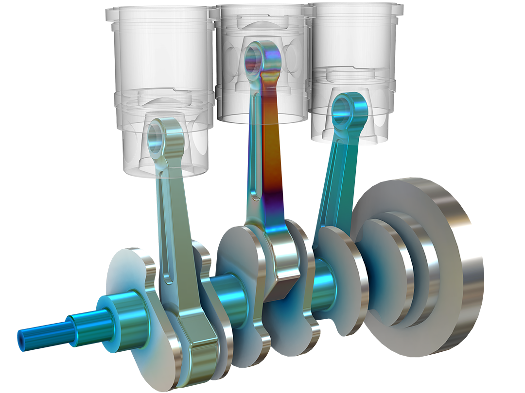
The Multibody Dynamics Module, an add-on to the COMSOL Multiphysics® software, provides an advanced set of tools for designing and optimizing 2D and 3D multibody systems using finite element analysis (FEA). The module has the ability to simulate mixed systems of flexible and rigid bodies to find the critical components in a system, all while saving computational effort. This enables you to perform more detailed component-level structural analyses in major application areas, such as automotive engineering, aerospace engineering, biomechanics, and more.

The module includes built-in multiphysics couplings that include acoustic–structure, solid–bearing, and fluid–multibody interactions. The multiphysics capabilities of the COMSOL® software make it possible to combine multibody dynamics with other physical effects, such as advanced heat transfer, fluid flow, acoustics, and electromagnetics. You can further extend your modeling to include nonlinear structural materials and CAD import functionality.

Contact COMSOL
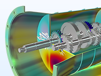
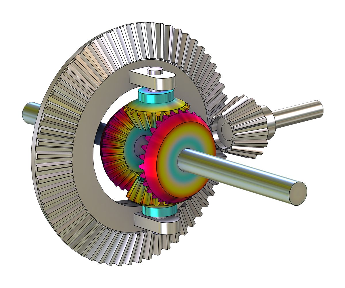
A differential gear model showing the displacement magnitude in the Prism color table.

Rigid and Flexible Parts

When modeling multibody systems, flexible and rigid bodies are connected using various types of joints, gears, cams, bearings, springs, or dampers and are subjected to large displacements and rotations. One of the advantages of using the Multibody Dynamics Module is how easy it is to mix rigid and flexible parts.

Generally, all or the majority of the parts in a multibody simulation are rigid and are thus represented by only the degrees of freedom of a rigid body. However, sometimes you may want to represent one or several parts as being flexible. With the material models available within the module, you can selectively assign rigid and flexible parts to your model to perform detailed structural analyses that include the effects of nonlinear materials. The Multibody Dynamics Module can be used, for example, to calculate forces experienced at the joints of the rigid parts of the structure as well as stresses generated in the flexible components.

Static and Dynamic Analyses

The Multibody Dynamics Module can be used for modeling the static and dynamic behavior of components that undergo combinations of translational and rotational motions with respect to one another. For dynamic models, you can perform various types of analyses, such as:

The module can be used to simulate, for example, the dynamics of transmission components like gears or chains. The results from a multibody analysis can then be used for other types of analysis, such as fatigue evaluation or acoustic analysis to find noise emitted by the system.

Some examples of quantities that can be computed are displacements, velocities, accelerations, joint forces, gear contact forces, and — in flexible parts — stresses. You can also model frictional contact between rigid bodies, which is much more robust and faster compared to a standard mesh-based contact.

Features and Functionality in the Multibody Dynamics Module

Find tools for designing and optimizing multibody systems in the COMSOL® software.

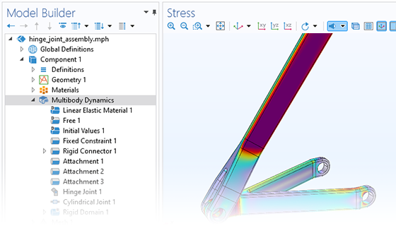
A close-up view of the Model Builder with the Multibody Dynamics node highlighted and a hinge joint model in the Graphics window.

Built-In User Interfaces

When working with multibody dynamics analyses, all steps in the modeling process are accessed within the COMSOL Multiphysics® environment. One of the most important tools in the Multibody Dynamics Module is the built-in Multibody Dynamics interface, which is used for modeling assemblies of flexible components, rigid components, or the combination of both. The available options cover modeling of various types of joints, gears, chain sprocket assemblies, and cam-follower mechanisms. Part libraries aid in building the geometry of the components. Meshing and solver settings are handled automatically by the software, with options for manual editing.

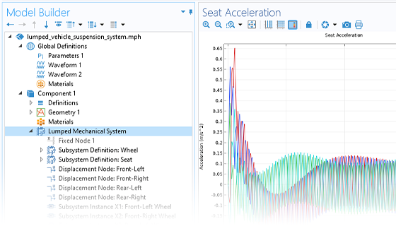
A close-up view of the Model Builder with the Lumped Mechanical System node highlighted and a 1D plot in the Graphics window.

Lumped Mechanical Systems

The Lumped Mechanical System interface is available for modeling an abstract mechanical system using a circuit representation with lumped components, such as masses and springs. The lumped components can be arranged in series or in parallel for analyzing displacements, velocities, accelerations, and forces.

The Lumped-Structure Connection multiphysics coupling can be used to insert these systems into finite element (FE) models built using any structural mechanics physics interface.

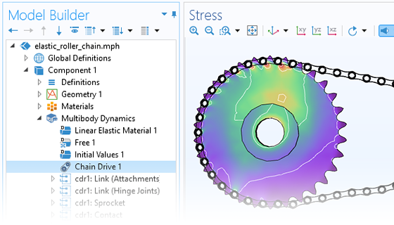
A close-up view of the Model Builder with the Chain Drive node highlighted and an elastic roller chain model in the Graphics window.

Chain Drives

A typical chain drive is an assembly of two or more sprockets with a chain wrapped around them that transfers mechanical power from one shaft to another. Using the Chain Drive feature in the Multibody Dynamics interface, you can model roller chain sprocket assemblies in 2D or 3D. This feature determines the interactions within a chain drive assembly and automatically generates a set of multibody dynamics features used for describing the assembly's behavior.

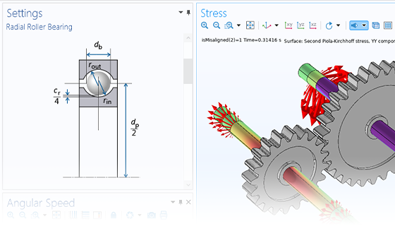
A close-up view of the Radial Roller Bearing settings and a gear model in the Graphics window.

Radial Roller Bearings

Roller bearings are often used for low-speed applications where noise is not an important consideration. These bearings have a limited life, especially in the case of misalignment, but can be easily replaced due to their low cost.

The Multibody Dynamics Module, together with the Rotordynamics Module, provides the following different types of predefined radial roller bearings in 3D:

  • Deep groove ball
  • Angular contact ball
  • Self-aligning ball
  • Spherical roller
  • Cylindrical roller
  • Tapered roller
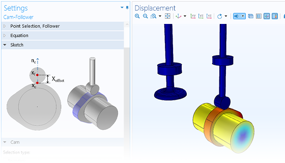
A close-up view of the Cam-Follower settings and a valve-opening model in the Graphics window

Cam–Follower Connection

The Cam-Follower connection feature is used for modeling a simplified contact by applying a bidirectional constraint between a cam and its follower. A cam–follower system is defined through a set of boundaries or edges that is being followed by a point. The cam can be defined on rigid bodies as well as elastic bodies. Thus, cam boundaries or edges can undergo any kind of rigid body motion or deformation.

This tool allows you to draw any user-defined cam profile as a geometry model and compute the follower motion in terms of displacement, velocity, and acceleration curves. It is also possible to compute the connection force at the contact point and hence, by looking at the sign of the connection force, predict an intermittent contact between the cam and follower.

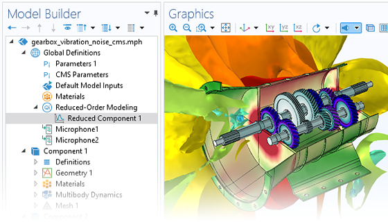
A close-up view of the Model Builder with the Reduced Component node highlighted and a gearbox model in the Graphics window.

Component Mode Synthesis (CMS)

In the Multibody Dynamics Module, it is possible to reduce linear components to computationally efficient reduced-order models using the Craig–Bampton method. Such components can then be used in a model consisting entirely of reduced components or together with nonreduced elastic FE models where the latter can then be nonlinear. The approach, which is called component mode synthesis or dynamic substructuring, can give large improvements in terms of computing time and memory usage.

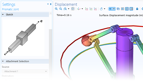
A close-up view of the Prismatic Joint settings and a centrifugal governor model in the Graphics window

Collection of Joints

For designing realistic multibody dynamics systems, the module includes a collection of predefined joints. The relative motion between interconnected multibody components is constrained according to the type of joint. The following joint types are available:

  • Prismatic
  • Hinge
  • Cylindrical
  • Screw
  • Planar
  • Ball
  • Slot
  • Reduced slot
  • Fixed
  • Distance
  • Universal

You can apply additional properties to the joints, such as elasticity, friction, constraints (allowing maximum movement), and locking.

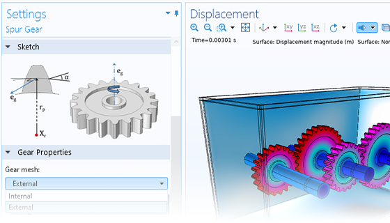
A close-up view of the Spur Gear settings and a gear train model in the Graphics window.

Collection of Gears and Racks

A collection of predefined gears and racks is included in order to easily and robustly create models of transmission systems with many moving parts. It helps in identifying the correct gear pair by automatically checking for the comparability criteria of correct gear-tooth meshing. The gears can be mounted on a rigid or a flexible shaft either directly or by using hinges and bushings.

In order to make a transmission system model more accurate and realistic, a gear pair can additionally include elasticity, transmission error, backlash, and friction. The following gear and rack types are available:

  • Spur gear, external
  • Spur gear, internal
  • Helical gear, external
  • Helical gear, internal
  • Bevel gear
  • Worm gear
  • Spur rack
  • Helical rack
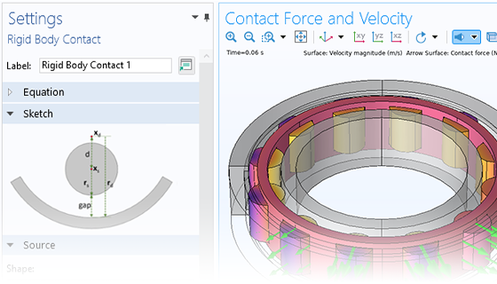
A close-up view of the Rigid Body Contact settings and a cylindrical roller bearing model in the Graphics window.

Rigid Body Contact and Friction

To model mechanical contact between rigid bodies, a Rigid Body Contact feature is available for modeling meshless contact between standard-shape rigid bodies. Depending on the shape of the source and destination bodies, different types of formulations are available:

  • Spherical to spherical
  • Spherical to cylindrical
  • Spherical to planar
  • Spherical to arbitrary
  • Cylindrical to cylindrical
  • Cylindrical to planar

In addition to the rigid body contact formulations, a general formulation is available for distributed contact between two bodies where at least one is flexible.

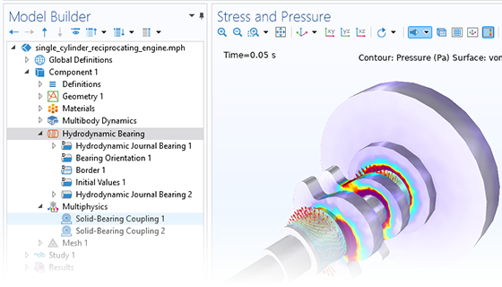
A close-up view of the Model Builder with the Hydrodynamic Bearing node highlighted and an engine model in the Graphics window.

Hydrodynamic Bearings

Performing multibody analysis of hydrodynamic bearings requires a coupling with the Hydrodynamic Bearing interface in the Rotordynamics Module. The interface is intended for analysis of fluid film bearings in 3D, efficiently modeled using a surface geometry. When both a Multibody Dynamics interface and a Hydrodynamic Bearing interface are present in the model, a Solid-Bearing Coupling multiphysics coupling is available and enables the modeling of the following journal bearings in a multibody system:

  • Plain journal
  • Elliptic journal
  • Split-halves journal
  • Multilobe journal
  • Tilted-pad journal
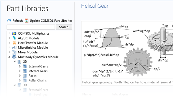
A close-up view of the Part Libraries in COMSOL Multiphysics showing an example of a helical gear geometry.

Part Library

The Multibody Dynamics Module contains a built-in geometry library for creating different types of gears, available in 2D and 3D. You can use them to build a gear tooth, a single gear, a pair of gears, or a gear train. All of the gear geometries are parameterized and the input parameters can be varied to customize the gear tooth or gear blank shape. To avoid building an invalid geometry, a feature is available that checks that the input parameter values are consistent.

Since the gear features are pure mathematical descriptions, the geometrical parts are mainly used for visualization purposes. It is, however, also possible to use them for detailed FE models. Similarly, parameterized parts for sprockets and roller chains are available.

Multiphysics Couplings for Extended Multibody Dynamics Analyses

Easily combine two or more physics interactions, all within the same software environment.

A close-up view of a gearbox model showing the normal acceleration.

Vibroacoustics

Perform multibody analyses to compute acoustic vibrations and noise.1

A close-up view of three power switch models.

Electromechanical Devices

Simulate rigid body dynamics under the influence of magnetic forces or induced currents.2

A close-up view of a disc brake model showing the temperature.

Thermal Expansion

Analyze frictional heating and thermal expansion.3

A close-up view of a set of rotors with helical gears.

Rotordynamics

Combine a bearing simulation together with a multibody simulation.4

A close-up view of a washing machine model in the Spectrum color table.

Structural Mechanics

Augment multibody dynamics models with general structural mechanics to model, for example, beams, shells, and nonlinear materials.5

A close-up view of an induction motor model showing the stress.

Electromagnetics and Vibration

Simulate electromagnetic effects and vibrations in 2D and 3D.2

A close-up view of a mechanism submerged in fluid showing the velocity field and pressure.

Fluid–Multibody Interaction

Model phenomena where a fluid and a rigid or deformable solid affect each other.

A close-up view of a rod showing the stress.

Fatigue

Perform fatigue analyses of critical flexible bodies.6

  1. Requires the Acoustics Module
  2. Requires the AC/DC Module
  3. Requires the Heat Transfer Module
  4. Requires the Rotordynamics Module
  5. Requires the Structural Mechanics Module
  6. Requires the Fatigue Module

Every business and every simulation need is different.

In order to fully evaluate whether or not the COMSOL Multiphysics® software will meet your requirements, you need to contact us. By talking to one of our sales representatives, you will get personalized recommendations and fully documented examples to help you get the most out of your evaluation and guide you to choose the best license option to suit your needs.

Just click on the "Contact COMSOL" button, fill in your contact details and any specific comments or questions, and submit. You will receive a response from a sales representative within one business day.

Next Step

Request a Software Demonstration