Examples of the General Extrusion Operator
The General Extrusion operator maps expressions defined on a source to an expression that can be evaluated on any destination geometry where the destination map expressions are valid. It can be used for a variety of different purposes, examples of which are presented here.
Extruding Data Along a Direction
Given an expression defined on a plane, e.g., the xy-plane, it is desired to map this data along the z direction.
To implement, define a General Extrusion operator on a boundary parallel to the xy-plane, with the z-expression blank for both the Source Map and a Destination Map. The General Extrusion operator will map data from the boundary into the volume, along the z direction, as shown in the following screenshots.
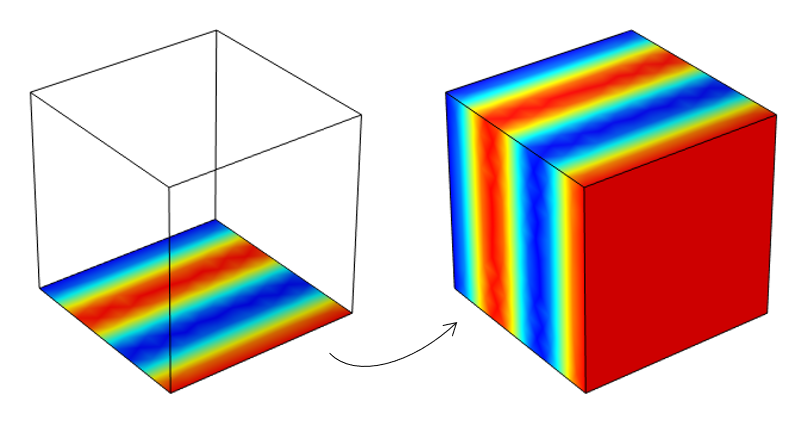
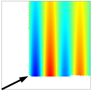
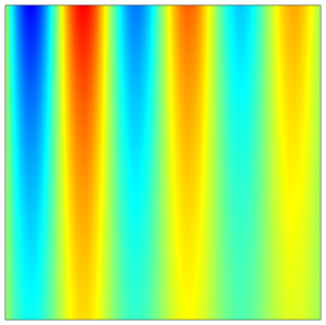
Mapping of data defined on a boundary (left) along the direction normal to the plane and into a volume (right).
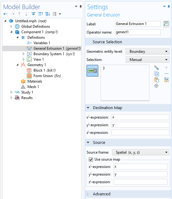
Settings used to map data from a boundary parallel to the xy-plane along the z direction.
It is also possible to define the mapping in terms of coordinate systems. For example, to map data from a boundary around a centerline, introduce a cylindrical system, and use those coordinate system variables to define the source and destination map.
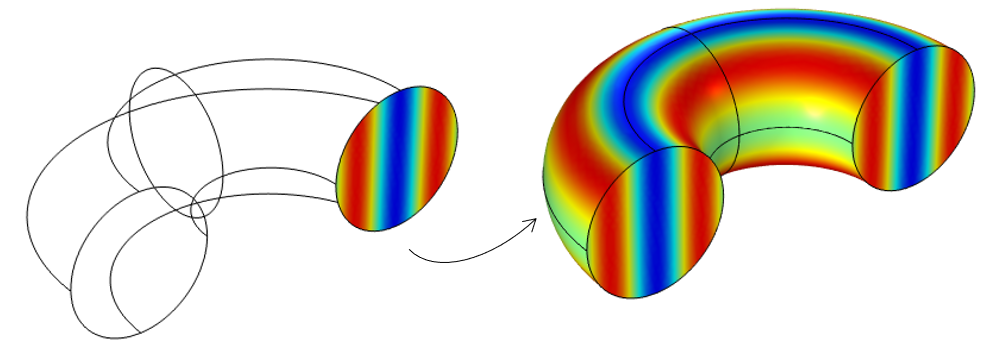
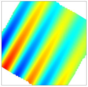
Mapping of data defined on a cross section (left) around an axis of symmetry and into a volume (right).
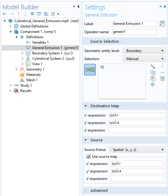
Settings used to revolve data about the azimuthal axis of a cylindrical coordinate system.
Transforms: Translate, Rotate, Mirror, Scale
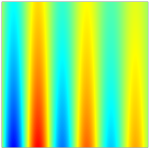
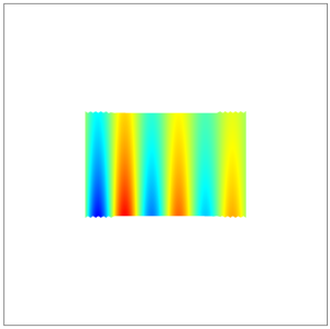
Sample data defined on the xy-plane, centered at the origin.
Considering a variable defined on the xy-plane within a unit square centered at the origin, as shown above, it is possible to implement a variety of transforms simply via different destination maps, and leaving the source map unchanged. Several cases are illustrated in the table below. The same transforms can be implemented in three dimensions.
| Type of Transform | Destination Map | Result |
|---|---|---|
| Translate | x-expression: x-0.3 y-expression: y-0.15 |
 |
| Rotate | x-expression: x*cos(30[deg])-y*sin(30[deg]) y-expression: x*sin(30[deg])+y*cos(30[deg]) |
 |
| Mirror | x-expression: x y-expression: -y |
 |
| Scale | x-expression: x*2 y-expression: y*3 |
 |
Other Uses of the General Extrusion Operator
- Coupling Physics Between Model Components for Multiphysics Models
- Mapping of data between different components in the model to perform submodeling
- Mapping between components to extract results on different geometries
- Computing distance fields
- Implementing a dynamic probe
- Nonlinear mappings
Submit feedback about this page or contact support here.