

When modeling a structure with beam elements, we don’t use the actual 3D geometry. Instead, we use a line model, which represents the other two dimensions through defining a set of cross-section properties. With the Beam Section Calculator simulation app, we can easily find the properties for a wide range of beam sections from European and American standards. The app also makes it simple to accurately compute the stress distribution for a given set of applied moments and forces.
Exploring the Beam Section Calculator
You can use the Beam Section Calculator as a utility tool to accurately compute a beam section’s properties and stress distribution or as a complement to a beam element model. This app can be downloaded with the Structural Mechanics Module, an add-on product to the COMSOL Multiphysics® software. There are two versions of the Beam Section Calculator. The first version uses only the Structural Mechanics Module, while the second version also uses LiveLink™ for Excel®.
While the first version of the app has a fixed amount of section data, the second version enables us to replace the section data list with a workbook in Excel® spreadsheet software. This process is explained further in this blog post.

The user interface of the Beam Section Calculator with LiveLink™ for Excel®.
The Beam Section Calculator provides data for about 9000 beam sections from American and European standards. The table below shows a few of the available beam section types.
| Beam Standard | Beam Shape | Beam Section Type | Description | American | I-beam | W | Wide flange beam |
|---|---|---|---|
| S | Standard Beam | ||
| HP | Bearing Piles | ||
| M | Miscellaneous beams | ||
| C-beam | C | Standard Channels | |
| MC | Miscellaneous channels | ||
| L-beam | Equal | Equal angles | |
| Unequal | Unequal angles | ||
| T-beam | WT | Wide flange tees | |
| ST | Standard tees | ||
| MT | Miscellaneous tees | ||
| European | H-beam | HEA | Wide flange beams A |
| HEB | Wide flange beams B | ||
| HEM | Wide flange beams M | ||
| I-beam | IPE | I-beams | |
| IPN | Standard beams | ||
| U-beam | UPE | Channels with parallel flanges | |
| UPN | Standard channels | ||
| L-beam | Equal | Equal angles | |
| Unequal | Unequal angles | ||
In the Designation section of the app, we choose the beam type through a multilevel sequence of steps. When we choose a beam standard, it updates the list of beam shapes. This in turn affects the beam types, as there are different types available for each shape. Once we’ve selected a type, we pick the beam designation from the look-up table, shown below, and make the beam units either imperial or metric.
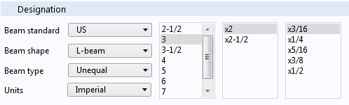
The Designation section, where we select the desired beam section.
The beam section geometry parameters are automatically updated in the Dimensions section, shown in the image below. To provide a visual of how the beam geometry looks, this section shows a sketch of its dimensions. We can also view a geometry with the appropriate scaling in the Graphics window on the left side of the app.
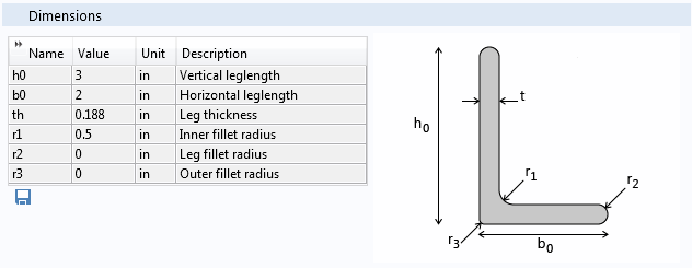
The beam geometry parameters in the Dimensions section.
Calculating the Beam Section Properties
In a computational structural analysis, beams are usually depicted with lines representing the center line. Instead of representing the cross section in the geometry, these specific elements use properties like area and moments of inertia. The Beam Section Calculator provides us with an accurate evaluation of these section properties.
After selecting the desired beam section, we click on the Compute button to get the section properties. The results are displayed in the Section Properties tab.
The only section property actually stored in the app is a minimum set of the sections’ geometrical dimensions; all of the other data is computed. For this reason, the tabulated values may differ somewhat from what is seen in a sheet from a beam manufacturer. The cross-section data computed in the app is exact, whereas values found in tables are usually based on approximate formulae.
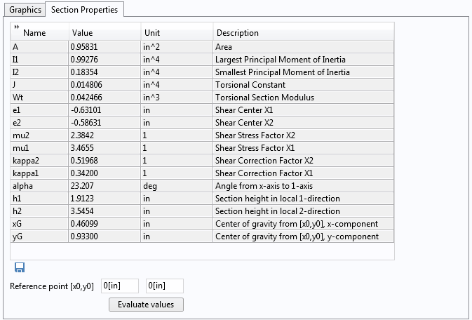
The computed section properties.
The beam section properties computed in the app are the properties used in the Beam interfaces and found in the Section Properties section. They account for the main properties that characterize a structural beam, including:
- Cross-section area (A)
- Coordinates of the center of gravity (xG and yG)
- Principal moment of inertia, largest (I1) and smallest (I2)
- Direction of the principal axes (alpha)
- Distance to shear center in principal directions (e1 and e2)
- Torsional constant (J)
For xG and yG, we can specify the reference point from which we want to evaluate these coordinates. No need to compute the solution again; we just click on the Evaluate values button. Regarding the direction of the principal axes, their orientations are given by the principal moment of inertia. Alpha corresponds to the angle between the global x-axis direction and the first principal axis (given by the largest principal value). As for the shear center, also known as the center of rotation, it is the point around which the shear stress from bending has no torque.
In addition, the Section Properties tab shows the stress evaluation properties, including:
- Section height in principal directions (h1 and h2)
- Torsional section modulus (Wt)
- Maximum shear stress factor in principal directions (mu1 and mu2)
The app also computes the shear correction factor in the principal direction (kappa1 and kappa2). This is a multiplier that makes the strain energy from the average shear stress and shear strain of the cross section equal to its true shear energy. We need this value when modeling shear flexible beams using the Timoshenko beam theory.
We can use the properties listed above in the Beam interfaces by clicking on the Save button to store the data in a text file. Uploading this file into COMSOL Multiphysics enables us to define the variables, which in turn helps us describe the cross-section data settings.
Computing Stress with the Beam Section Calculator
When using beam elements, the stresses computed are conservative, only considering the worst case of stress interaction. This is because we don’t know the actual geometrical shape of the cross section, only its properties (as described above).
The Beam Section Calculator uses the true section geometry of the beam, including any fillets. With a set of section forces, it is thus possible to accurately compute the stress distribution within the section.
In Input forces, we enter the set of forces to be used in the stress evaluation.
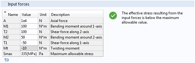
The Input forces section.
To set the forces after calculating the section properties, we simply update the stress in the Graphics window by clicking on the Update plot button. In addition, we can specify a maximum allowable stress, to which the app compares the equivalent stress. If the stress is above the allowable specified value, it displays a warning message.
To visualize our results, there are a few plots that we can choose from. Bending Moment plots the bending stress caused by a moment around the principal axes. This option also shows the orientation of the principal axes. The coordinate system of the principal axes is located at the section’s center of gravity.
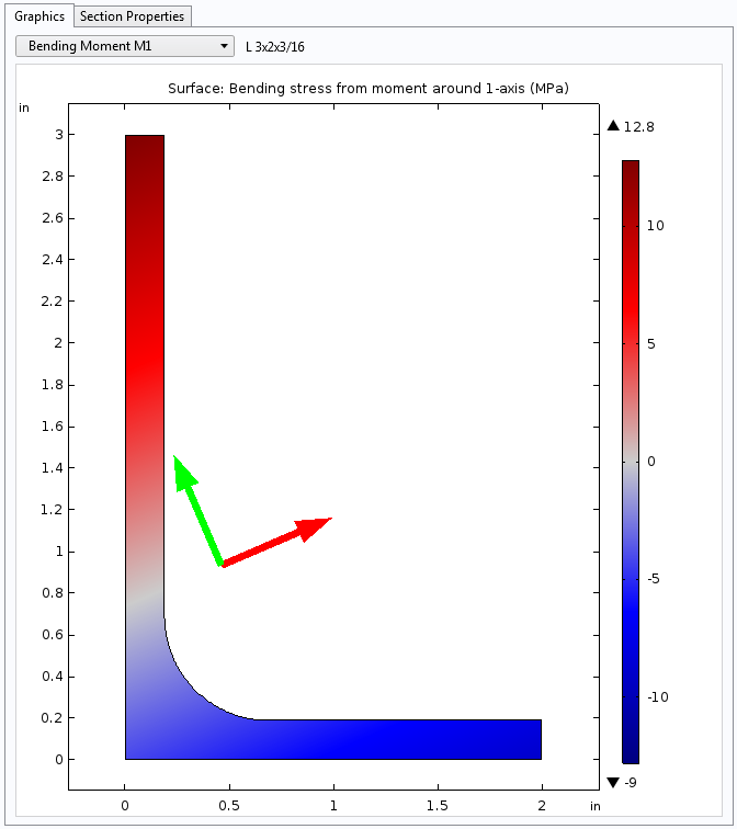
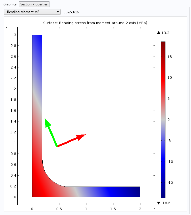
The bending stresses from moment around 1-axis (left) and 2-axis (right).
Shear Force displays the shear stress caused by a shear force along the principal axes. The surface plot shows the shear stress resultant, while the arrow plot shows its orientation. In addition, the location of the shear center is shown as a red dot.
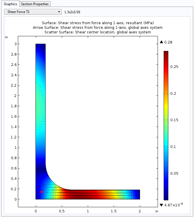
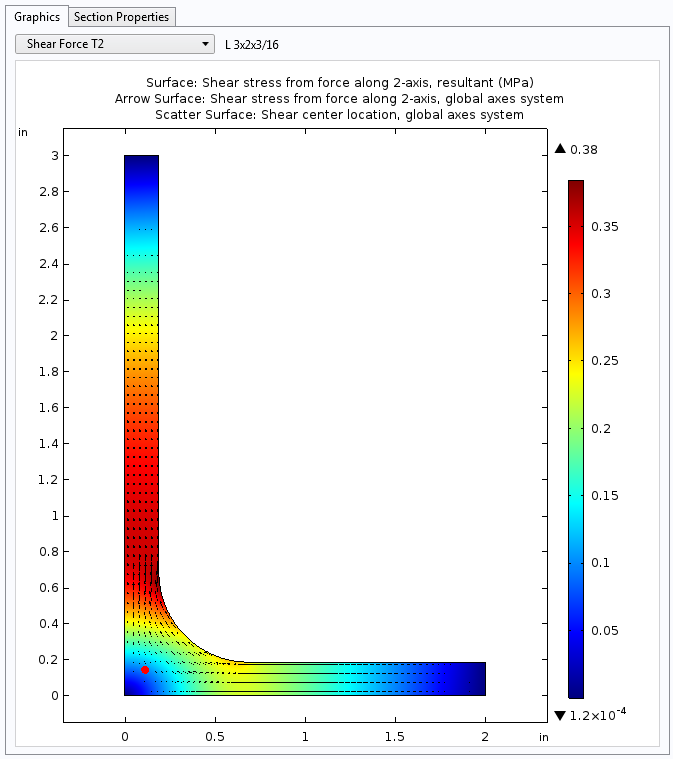
The shear stresses from a force along 1-axis (left) and 2-axis (right).
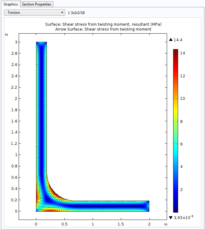
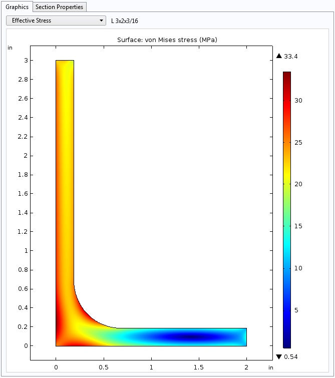
Torsion plots (as shown below on the left) show the shear stress caused by a twisting moment. As with the Shear Force plot, the surface plot displays the shear stress resultant, while the arrow plot shows the orientation. Equivalent Stress plots (as shown below on the right) show the von Mises stress (MPa).
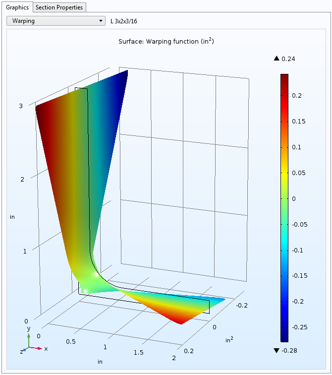
Additionally, Warping, shown below, plots the out-of-plane deformation caused by torsion.
Replacing the Beam Section Data with LiveLink™ for Excel®
When using LiveLink™ for Excel®, we can manually edit the list and dimensions of the beam section that we want to use. Clicking on the Replace sections button uploads the Excel workbook containing the new beam section data. This lets us add beams from another standard.
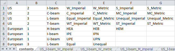
The contents worksheet in the beam section data file.
This workbook follows a specific format. First, it must contain a worksheet named contents, which provides the structure for the app’s interface. The first column defines how the beam is described in the Beam standard combo box. As for the second column, it contains the number of design parameters (up to three) that define the beam designation. For instance, an American beam is usually defined with two parameters (W 4×13), while a European beam typically only uses one parameter (HEA 100). This determines the number of list boxes in the designation section.
The third column describes the Beam shape combo box and should correspond with one of the generic beam geometry parts in the model, including:
- I-beam
- H-beam
- C-beam
- U-beam
- T-beam
- L-beam
In the fourth column and after, we enter the name of the beam section type. To specify the beam dimensions with a different unit system, we add the unit name to the section type, separating the names with an underscore.
For each beam section, the dimensions are stored in a separate worksheet. The name of the worksheet corresponds to the full description of the beam type, including the standard name, beam shape, and beam type, with each separated by an underscore. As an example, the worksheet name for a UPE European beam is European_U-beam_UPE.

A section-type worksheet in the beam section data file.
After the beam section data is replaced, the workbook is automatically stored in the .comsol/ directory. Every time the app starts, it asks whether we want to use this user-defined workbook or an embedded one. To avoid this notification, we can save the app and choose to embed the modified workbook. To get back to the original beam section data, we click on the Reset all button.
Coding for the Interface of the Beam Section Calculator
Let’s turn our attention to the inner workings of the Beam Section Calculator. This information is not necessary for using the app, but as with any app distributed with the software, it is interesting to look behind the scenes.
The app’s dynamic interface helps us to easily navigate through the multiple beam sections. After selecting a value in a combo box, the combo box that appears next automatically populates with the appropriate values.

Code for populating the combo box in the Beam Section Calculator.
The code above runs when we change the value in the Beam Standard combo box. Whether we choose a European or American option, the choice list shapeList is populated with the right values. String arrays define the list for each combo box when the app starts.

Code showing how the structure of the combo boxes is initialized.
The list box contains the design parameters used to define the beam geometry parts. The list of values is associated with a specific beam section type using a HashMap table. We can define this table as a utility class.

The HashMap table, created in the Application Builder as a utility class, associates string arrays with string inputs.
We can store a large amount of data this way as long as we don’t plan on replacing it. Or, we can use LiveLink™ for Excel® to read the data from a workbook embedded in the app. As this version of the app has a different structure, it allows the interface to be more flexible. It reads a workbook, which can be manually edited.
 method")
The readExcelFile() method enables the app to read the contents of a worksheet.
The readExcelFile() method transfers the data from an Excel workbook to a string in the app. The method then reads the worksheet’s contents, which contain the structure of the combo box. The geometry data for each beam type is stored in separate worksheets.
The Underlying COMSOL Multiphysics® Model
Now that we’ve explored the app itself, let’s discuss the underlying model. The Beam Section Calculator uses the Beam Cross Section interface, which is part of the Structural Mechanics Module, to analyze beam sections.
We can create a beam section geometry with a beam geometry part from the Part Library. Here, we find principal shapes for European and American standard beam sections as well as generic beam shapes. These geometry parts use multiple parameters to control all of the section’s dimensions, while the classical standard beams use designation parameters (for example, entering 10 and 15.3 as parameters gives a standard C10x15.3 beam cross section). The generic beam geometry part is fully parameterized so we can generate any section.
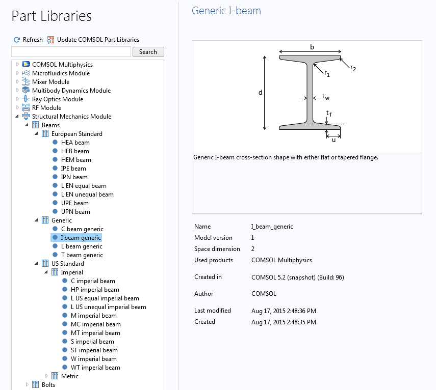
The beam geometries in the Part Library of the Structural Mechanics Module.
When selecting a beam in the app, it provides the geometry part with the corresponding input parameters. The version of the app with LiveLink™ for Excel® uses generic beam geometry parts. This enables us to easily redefine our own beam section.
Ready to try out the Beam Section Calculator app on your own? Click the button below to get started.
Further Resources
- Read more about using apps for structural analysis on the COMSOL Blog:
- Watch a video that walks you through modeling structural mechanics in COMSOL Multiphysics
Excel is either a registered trademark or trademark of Microsoft Corporation in the United States and/or other countries.


Comments (0)