Compact Antennas for Digital TV Reception on Mobile Terminals
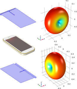
With the Release 14, the Third Generation Partnership Project (3GPP) [3GPP TR 38.913 V0.4.0, 2016] paved the way to the possibility of delivering digital television services on mobile terminals, such as smartphones and tablets, overcoming all the limitations which characterize the previous releases. From the point of view of the physical receiving terminal, this poses a great challenge for the antenna designers, due to the wide band to cover with a sufficient return loss, i.e., the whole digital terrestrial television (DTT) band (470-694 MHz), and the limited volume available for the antennas on a mobile device. To deal with the limits on the achievable bandwidth characterizing the performance of small antennas, the only solution seems to be the possibility to excite the characteristic modes of the ground layers and metal shielding of the entire device (i.e., the so-called chassis) by means of properly-shaped coupling structures [J. Holopainen et al., IEEE Trans. Antennas Propag., vol. 58, 2010]. In addition to the configurations proposed by Holopainen et al., with the coupling element (CE) placed on the short edge of the chassis, we analysed the excitation of a higher characteristic mode of the chassis via a CE located on the long edge [R. Gaffoglio et al., 13th European Conference on Antennas and Propagation (EuCAP), 2019]. Here, we present some results concerning the experimental implementation of these prototypes, comparing the achieved performance to the simulations obtained with the COMSOL Multiphysics® software. Two prototypes have been experimentally realized: a smartphone-type chassis with dimensions 135 mm x 75 mm x 5 mm, with the CE placed on the short edge, and a bigger smartphone-type model with dimensions 160 mm x 90 mm x 5 mm and the CE positioned on the longer edge. The CE structure simply consists in a folded metal sheet forming a sort of stair step with a height of 5 mm. Both the prototypes have been modeled in COMSOL Multiphysics® using the RF Module and reproducing the experimental feeding near the CE element by means of a coaxial cable excited by a Lumped Coaxial Port. A good agreement was found between the S11 curves and the radiation patterns provided by COMSOL Multiphysics® and the experimental measurements obtained using a VNA and a compact bench-top electromagnetic scanner (EM-Scan RFX) that allows a real time antenna characterization in the laboratory environment. For these antennas, the reliability of the S11 curve is crucial, since it is used to evaluate the matching circuit elements needed to properly shift the resonant behavior from 1 GHz to the center of the DTT band. Finally, the performance of the considered CE-based antennas has been compared to that of a planar inverted F-antenna (PIFA), optimized to show a self-resonant behavior across the DTT band by means of a genetic algorithm implemented in COMSOL Multiphysics® using the LiveLink™ for MATLAB® Module.