
Nonisothermal Flow
Isothermal vs. Nonisothermal Flow
By definition, isothermal means to have a constant temperature. In many engineering applications, we can assume that a fluid's temperature will remain constant because variations are either very small or inconsequential in magnitude compared to other physical variations in the application.
Being nonisothermal flow refers to fluid flows with temperatures that are not constant. When a fluid is subjected to a temperature change, its material properties, such as density and viscosity, change accordingly.
In some situations, these changes are large enough to have a substantial influence on the flow field. And, because the fluid transports heat, the temperature field is, in turn, affected by changes in the flow field. This two-way coupling between fluid flow and heat transfer is a phenomenon that is prevalent in heat exchangers, chemical reactors, atmospheric flows, and processes in which components are cooled.
Examples of Nonisothermal Flow
Light Bulb
A noble gas, such as argon, is often used within light bulbs to convect heat away from the tungsten wire and prevent it from burning up from the Joule heating effect it is subjected to. As the gas in the vicinity of the filament becomes hotter, its density becomes relatively lower than the rest of the gas in the bulb, and it rises upwards due to imposed buoyancy forces.
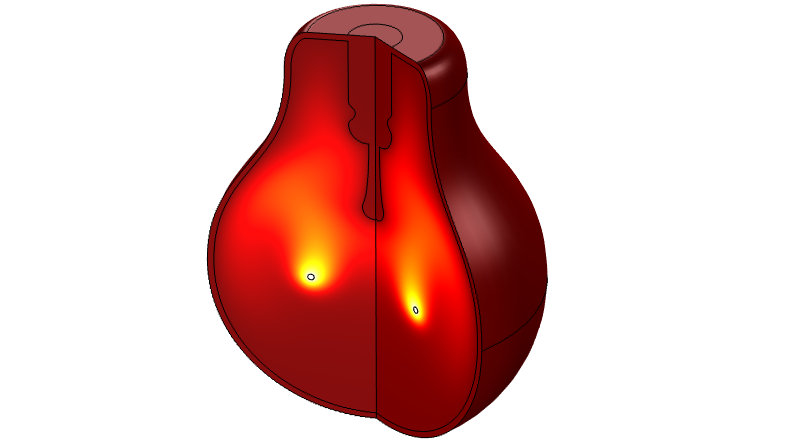
The induced flow transfers heat from the filament to the rest of the gas in the bulb and then to the glass of the light bulb. The coupled phenomenon between heat transfer and flow that develops inside the bulb is also referred to as natural convection.
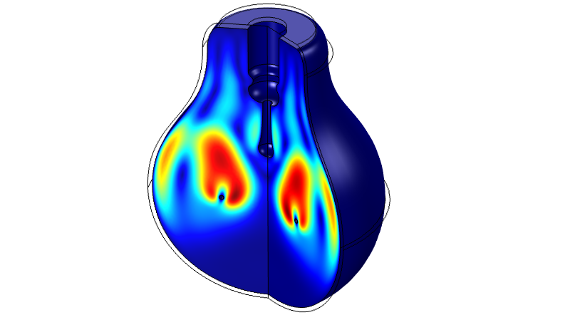 Model highlights the motion of the gas within the bulb.
Model highlights the motion of the gas within the bulb.
Model highlights the motion of the gas within the bulb.
Heat Sink
Another example of nonisothermal flow illustrates forced convection in an aluminum heat sink. Heat sinks are used to increase the surface area of components that need to be cooled. The larger the surface area, the more effective the cooling. If this can smartly be made to occur within a compact volume, the cooling device will also be more efficient.

Heat transfer from the heat sink to the cooling air.
Heat transfer from the heat sink to the cooling air.
In the example shown, thermal energy is transported through conduction in the aluminum heat sink and through conduction and convection in the cooling air. The convective cooling effects of the heat transfer process effectively prevent components from overheating or failing. Once again, the heat transfer's effect on the velocity vector needs to be considered, and the nonisothermal flow needs to be simulated.
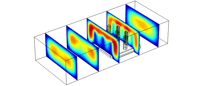 Image depicts the velocity field around the heat sink.
Image depicts the velocity field around the heat sink.
Image depicts the velocity field around the heat sink.
Last modified: February 21, 2017